First own eurorack module released
Yes! Released the first eurorack module from my own startup company “sinneb musical technology”. For now I only have one, which I used to create the demovideo and the poster. I’m ordering components so a first batch of 8 modules should be available soon. Please check my instagram for information regarding availability. Here are the Eagle schematic and board files for both the frontpanel and the components PCB:Domain Change
The sinneb.net domain expires in a couple of weeks. Since I’m more and more using social media to show progress and be in touch and furthermore only keeping the contents of my blog archived for reference, I decided to cancel my contract with the webhoster and switch to a static page on github pages using the Hugo framework. Sorry for the broken links, you can easily use your browsers search on the homepage to find what you need - each post is listing with the first 200 characters or so.a modern take on the exponential converter
In the previous post, I investigated the possibility to replace the CA3046 and expo pair with modern components in a synthesizers’ exponential converter, while retaining the temperature compensation. Continuing on the findings from the previous post, I worked out a schematic: CV inputs are summed in opamp U7, then scaled with regard to temperature over R1 through R4 for the expo converter build up out of a BCM847DS matched transistor pair.Replacing the CA3046 & understanding and replacing the tempco
Let’s get rid of the CA3046, because it’s large and almost obsolete, even the one in a SOIC package (LM3046). The temperature dependant resistor (tempco, 1k, 3300ppm) is also obsolute and very hard to source – so let’s also get rid of that. On this blog, the CA3046 part has been examined in depth, but the tempco part can use some investigation. First the CA3046, a General Purpose NPN Transistor Array.bennis|budge VCO v2.0 smd finished!
After a number of important revisions, the very first reliable, stable and interesting VCO is finished! Some features: – Instead of a classic configuration where the sawtooth core is reset by a voltage comparator and a small capacitor, this sawtooth core is reset by a Schmitt trigger configuration, allowing LFO functionality by switching on an extra capacitor in the sawtooth core. This because the reset pulse does not rely on the size of the reset-capacitor but is determined by the Schmitt trigger.New VCO prototype: bennis|budge VCO v1
So, finally I combined all experiences and experiments of the last couple of years into a new VCO prototype. And, IMHO it rocks! In this post you’ll find some development notes, the LTSpice simulation files and the Eagle schematics and board design. The Eagle files correspond to the actual prototype version, the LTSpice simulation is already an iteration further. See following notes for the differences. VCO prototype schematics png (viewable in browser)Serial midi on the Raspberry Pi Zero W
The Raspberry Pi Zero W (rpi0w) has a lot of properties to make it a great musical instrument (CPU power, affordability, portability, power demands). First thing on my list is serial MIDI in, to hook up my octatrack. I compiled the following guide to equip the rpi0w with MIDI in. Software Install Rasbian (my version is 2017-04-10) Midi requires the serial device “/dev/ttyAMA0” to be exposed through the rpi0w’s header pins.Development with STM32F7 discovery
A few pointers regarding development with an STM32F7 discovery board. My intention with this powerful board is to be able to sync wave files to a tap-tempo BPM (kinda Ableton Live like), and take the device up on stage with my band. The board: The STM32F7 disco runs at ~200Mhz, has support for DSP instructions (hardware floating point unit) and a lot, lot more. My first step was to make development easy, fast and “Arduino” like – since I’m really comfortable with that.Matrix mixing craziness
A few weeks ago I did a small experiment with summed matrix mixing: sounds great, crazy, untamed etc. I decided to explore summed matrix mixing a little bit further and today I started building a new prototype, that got out of hand quickly! A single attenuverting channel (a 1 to 1 matrix) looks like this: Although interesting, a more advanced matrix would offer a lot more possibilities. I decided to go for a 4 x 3 matrix, since I had those parts available.Schematics, eagle files and build notes for the umodular
As promised, attached to this post you’ll find the schematics in PDF and the eagle files for the umodular. Released as open source hardware, so hack away and please provide feedback! The eagle designs are not editable using the free version because of the size of the PCB, sorry. Check the list below; one of the outstanding wishes is to divide the large board into smaller, attachable boards – all below the 100mm x 80mm constraint.µ-modular demo on YouTube
There you go! Sources, designs etc coming soon!edusynth, the boards!
Boards have arrived from China, PCBWAY.com. Fast service! Ordered 10 board 24 hour rush on friday night because of Chinese new year and tuesday (today) the boards have arrived already. Boards look great, unfortunately green because of the 24h rush service but good quality. Unfortunately I made some errors, which I’ll document here for future reference. The picture above shows the board missing Eagle layer 25 (tNames) which I used to designate the input and outputs pins… Illustrated below:edusynth, getting there!
Making progress! Because of the start of a new semester at my university, I tried to finish a first version of the edusynth. And, also to my own amazement, I did! Here’s a first 3d brd view of the eagle file: Dual VCO, VCF and VCA. Dual ADSR and a number of OPS (CV, mix and split). Board are ready according to pcbway – I’m waiting for delivery… First try outs to follow.edusynth, successor to senk
Not out yet and already succeeded… poor Senk ;) Anyways, now presenting edusynth with an updated VCO design because the previous design had bad performance over 500hz. Also, hardsync is an option here and sounds absolutely great! Here’s the ltspice schematic: and the amplifier and output section: understandable and low part count. Nice.Senk, a 5v µModular
Been busy building a 5v µModular system for students to learn about and experiment with sound. Design should follow the classic synth setup like for example a Minimoog, with added patchpoints. Part of the design is finished, as follows: Input of 1 is an Arduino PWM wave. This wave is passively filtered to a DC voltage (ranging from 0v to 5v). This resulting voltage will be one way to drive the voltage controlled oscillator.A temperature controlled CA3046
So, finally started work again on the heated CA3046. First, the results of the previous post regarding the CA3046 were reexaminated. Indeed, when building the schematic from that post: and heating that circuit with a hair dryer: the base voltage of the NPN transistor changes along with the temperature. The next step I took was connecting that output to an opamp comparator to be able to switch a heating circuit on and off.SSHing to a Raspberry Pi behind a firewall (Eduroam)
The firewall at my university (Eduroam) prevents direct connections between two computer on the network on all ports. SSH-ing to an other computer is therefor not possible. However, when a connection is ESTABLISHED, this connection can be reused – for example the other way around! Let’s work on this. Requirements: rpi, external server Automate your ssh login from your rpi to your external server using (this link). Execute these commands using “sudo” because the startup script we’re going to edit is run as root.Raspberry pi as high quality LFO generator
I’ve been experimenting with external LFO generators to modulate my MS20 mini. Working towards a small and portable solution, I first built a larger format prototype using my laptop, a Presonus Firestudio and a fresh copy of pyo (a Python module written in C to help digital signal processing script creation). Nice results! But I want a smaller, dedicated device to generate a variety of LFO waveforms, with enough range in the frequency (say from 0.LittleBits synced to Volca Beats’ pulse clock
Recently I was fiddling with a set of LittleBits and I was trying to sync these (the LitteBits micro sequencer that is), to my Volca Beats. With the current lineup of LittleBits, this was impossible. Since the Volca Beats has a sync out (0V, 5V pulses with 15ms duration), the solution was not all too difficult. I just took a LittleBits wire, cut it in two, reconnected the VCC and the GND but connected the SIG to the signal connector of an 3.The heated CA3046, part 1
A reliable VCO needs a steady exponential converter. Exponential converter are, because of their transistor based design (needed for the exponential functions), very temperature sensitive. A number of solutions to this problem exist. A solution that looks very interesting from a technical point of view is the solution found in (among others) the Moog Prodigy. The exponential converter only needs two transistors (the matched pair) from the five transistor available in the CA3046 chip.LM13700 Triangle VCO
The LM13700 OTA chip has an interesting schematic for a triangle VCO in its datasheet. The discreet sawtooth VCO I’m building is too complex for breadboarding and does not deliver a decent sawtooth (probably due to distortion picked up somewhere in the breadboard). Therefor I decided to give the LM13700 triangle VCO a go. The schematic in the datasheet is very clear. All I did was exchange some resistor and capacitor values to ones that I have laying around.Building an exponential converter
In this article I’ll describe the steps I took to design an exponential converter. YMMV of course, but I think this article is a good start and may provide some useful guidelines. The following table shows the relation between Hertz and wavelength. These are the MIDI C notes per octave, in Hz with their corresponding wavelength in ms 8.1757989156 hz 122.312205856 ms 16.3515978313 hz 61.156102927 ms 32.7031956626 30.578051464 65.4063913251 15.289025732 130.SPI control of AD9833
A few months ago I ordered a MSOP to DIP conversion board including an AD9833 from proto advantage. The AD9833 (LOW POWER, 12.65 MW, 2.3 V TO +5.5 V, PROGRAMMABLE WAVEFORM GENERATOR) looks like an interesting IC, doesn’t cost too much and is perhaps suited for a musical purpose. Wiring up and controlling the AD9833 took some time and some research but I finally combined the right pieces of the puzzle.Calculating Landolt C ring size based on the visual acuity
Landolt Ring Tiny Python script to calculate the size (5d) in meters of a Landolt C ring based on the visual acuity belonging to that ring. # determine Landolt C ring size based on decimal visual acuity scales # argument: visual acuity [0.1 ... 3] # result: size of Landolt C ring (5d in the image) (in meters) # http://upload.wikimedia.org/wikipedia/de/2/27/Landoltring.jpg import math, sys # distance from ring in meters distance = 5 print 2*distance*math.Kivy and vite-vite
Note to self: Use Kivy (Open source Python library for rapid development of applications for multiple platforms) and vite-vite (Toolkit for building business and productivity apps on Android using the Kivy framework) for next prototype.Livestream webcam via webm to browsers
Here’s a work in progress: livestream webcam video to browsers using Node.js. From here. Ubuntu requires the ‘nodejs’ executable instead of just ‘node’ var express = require('express') var net = require('net'); var child = require('child_process'); var cmd = 'gst-launch-0.10'; var args = ''; var options = null; var app = express(); app.get('/', function(req, res) { var date = new Date(); res.writeHead(200, { 'Date':date.toUTCString(), 'Connection':'close', 'Cache-Control':'private', 'Content-Type':'video/webm', 'Server':'CustomStreamer/0.0.1', }); var server = net.USB/IP under Ubuntu
USB/IP is a general USB device sharing system over IP network. Unfortunately, on newer Ubuntu’s the usb/ip device driver isn’t compatible with the userspace tools. Here’s how to fix this on Ubuntu 12.10 (and probably some older versions). Grab Linard Verstraete’s script from launchpad. Change the last line from sudo ln -s /usr/local/lib/libusbip.so.0 /usr/lib/libusbip.so.0.0.1 to sudo ln -s /usr/local/lib/libusbip.so.0 /usr/lib/libusbip.so.0 and run the script. You now have a compatible device driver and userspace tool.reminder: fixing locale warning on ubuntu
Just a quick reminder how to fix the locale warnings on fresh ubuntu installs. Warnings look, among others, like this: locale: Cannot set LC_CTYPE to default locale: No such file or directory Fix: add this LANG="en_US.UTF-8" LC_MESSAGES="C" LC_ALL="en_US.UTF-8" to /etc/environment Thank you MCKelvin @ askubuntuSawtooth VCO design
Time for a new post and I have an interesting prototype to share with you. Tom Wiltshire over at electric druid (http://www.electricdruid.net/) made a great writeup about the Roland Juno DCO workings (a true must read). Based upon the diagram I decided to give it a go. _from http://www.electricdruid.net/, used with permission._ I did some redesign work, since an Arduino is a very handy a capable device for such applications.Control CD4021 and 74HC595 over the same SPI bus
Working on a project I needed extra digital in’s and extra digital out’s for my Arduino Uno (lots of LEDs, lots of buttons). I’ll use a CD4021 to extend the digital in’s and a 74HC595 to gain extra digital out’s. I decided it would be best to both access the data of the CD4021 and send data to the 74HC595 over the hardware SPI bus on the Arduino (see previous post).Arduino, CD4021 and SPI
The “ShiftIn” tutorial on the Arduino site (Parallel to Serial Shifting-In with a CD4021BE) is very clear on why and how to setup and test your Arduino in combination with a CD4021 IC. I needed extra digital inputs and decided to communicate via SPI with the CD4021 chip. Figured it out, it was actually pretty simple thanks to the easy SPI implementation in the Arduino software since version 0020 or so (?LCD optimizations and additions
One of my first posts contains a LCD prototype. Today I needed LCD functionality and made some optimizations and additions to the LCD prototype. Speed up In the LCD3Wire library, I removed two delays: 131c131 < //delay(1); --- > delay(1); 155c155 < //delayMicroseconds(1); --- > delayMicroseconds(10); This gives a good speed increase when using the LCD3Wire library. Furthermore, reading this post (http://solar-blogg.blogspot.com/2009/02/displaying-custom-5×8-characters-on.html) I copied the code to the Arduino and displayed my own custom character (using the LCD3Wire library)Impressed by Thor!
Wow! I decided to give Reason 6 a good try. First of all I wanted to recreate the sound of my last analog prototype (see and listen to the previous post). Oh, here’s a picture of that prototype btw: In Thor I recreated the sound of a single analog oscillator like so: A single Analog Osc generating a sawtooth waveform, no filters, enveloppe only sustain. Sounds… the same! Listen for yourself:New synth in the works
and here’s an audiofile with a sneak preview of one of the VCO’s. vco1_test1 This sawtooth is generated through an orange drop capacitor (sounded better then its wima counterpart) in a 100% analog sound path. Reset pulses are generated by an Arduino and the rise of the sawtooth waveform is controlled by a MCP4921 DAC. Each frequencies requires an exact voltage to level out the sawtooth. I haven’t calibrated these voltages yet so the sawtooth isn’t very precise yet.beta juno106 filter replacement!
Juno-106 filter replacement (beta, sounds very ok!) by sinneb The filterpart, 4 pole low pass with resonance. Download LTSpice schematic file: juno106BetaFilterReplacement_FilterPart (pdf version) The exponential current source. Leave 10 ohm resistor out when connecting to filterpart. Download LTSpice schematic file: juno106BetaFilterReplacement_ExpoPart (pdf version) The VCA of this beta filter was built like the schematic supplied by Mooger5 (check older posts). The redesigned VCA based on a LM13700 should work also (check older posts).“tuned” the LPF
Yesterday I tuned the LPF using my trusty old board o’ potentiometers… Best sounding values came out like this: which I, after some thinking, recognized as the original values like in the JUNO6! Very nice! Just had to replace the 100pF capacitor with a 240pF capacitor like in the original. Only thing missing is the “mystery resistor” on the + input of the OTA to ground. For now I just left this res out.working combination!
Got a working combination of the expo converter and the 1 pole low pass filter. Sounds nice, although the expo needs some tuning. listen: Juno106 1pole replacement filter, for now only cutoff by sinnebredesigned the expo converter, again
The output current of the expo converter is now (100nA < Iabc < 2mA) which means a more logarithmic response of the VCF, more like the IR3109. btw this is a one pole LP filter, not a two pole VCF sound like this now: Juno2poleFilter-v2 by sinneb and here’s the real 2 pole LP filter: Juno2poleFilter-v3-real2pole by sinneb2-pole LM13700 lowpass filter working?
I’m not sure. Did a lot of prototyping and these are the results. Since I couldn’t figure out a proper way to calculate the cutoff frequency when using different current and resistor combination, I decided to use the default lowpass filter circuit from the LM13700 datasheet. Hooked my expo converter up to pin 1 (100nA < Iabc < 1.1mA) and started testing. The Vout of this pole is the Vin of the second pole.expo converter working!
Yesterday I breadboarded the expo converter from the previous post and it’s working! Current values were a little off; probably because I used 5% resistors. Will rebuild using metalfilm resistors.re-redesigned the expo converter
Previous design had resistor values of 4700k, impossible! So I redesigned the expoconv with a couple of voltage dividers.Redesigned the expo converter
As seen in the previous post, the following formula determines the cutoff frequency of the typical LM13700 lowpass filter design: The only variable part in this formula is the Iabc part, the incoming current from the expo converter. The cutoff frequency of the JUNO106 filter varies between 5Hz and 50000Hz (from the manual). To achieve this, Iabc low and Iabc high must differ a factor of 10000. I redesigned the expo converter as following:designing the filter
Current project status: Using the FREQ slider on the JUNO106 results in a exponential filter control current from 32nA to 705µA. So, when feeding 32nA into the filter, its cutoff frequency should be 5Hz. Feeding the filter 705µA results in a 50kHz cutoff frequency. My LM13700 lowpass filterdesign is based on the lectures by Aaron Lanterman. This is a typical design: resulting in the following plot (Iabc = 1mA)exponential converter current source
I reversed the current direction by using PNP transistors instead of NPN transistors (plus some other minor alterations). I also realized that the output current of the expo conv in the previous post (7mA) was way too high for the LM13700 (max current 1mA) so I adjusted the resistor in the iref connection to 10 megaohms! Max output to the LM13700 is now 705µA. The schematic: plot (current source leads to negative figures in LTspice)expo converter prototype… working!
Working! When moving the VCF FREQ slider from 0 to 10, the current varies from 0.3 UA (300 nA) to something above 7 mA. Looks pretty correct. Only thing I’m worrying about is the current direction. This expo is a current sink but I think I need a current source…80017a / ir3109 exponential converter
Completed the exponential converter for my open source Juno 106 filter clone. Mostly based on the great lectures by Aaron Lanterman (ECE4893A: Electronics for Music Synthesis, session 9, Exponential Current Sources). Also based on the SMR-4 filter as designed by mutable instruments. You should really check out Olivier’s work for Mutable instruments, great stuff there and the Shruthi-1 synth is just a fantastic piece of engineering. Very inspiring. On the the expo converter.80017a measurements
Found a working multimeter: As you can see, my assumption in the previous post regarding the current on VCA CONT was wrong. Max current is not 0.5mA but 0.3mA which will lead to a different value for r3 (the current to voltage resistor).VCA part done (well almost)
80017a VCA open source hardware replacement is done for about 95%. Original Roland: See previous post for Mooger5’s working BA6110 IC solution. Since I’m going to use the LM13700 OTA for the filter part, I figured the VCA would be a nice exercise in OTA building. To fully understand the inner workings of an OTA, I followed great lectures by Aaron Lanterman on Electronics for Musical Synthesis! My VCA version:Progress…
Long time no post. Sorry, real-life is sometimes getting in the way ;) Recently I bought a Leaflabs Maple R5 to replace my Arduino’s. I really like it. Eventually I ported ChibiOS (realtime OS) to it and tried some software filter algorithms from musicdsp.org. Didn’t make me happy; 72Mhz isn’t enough to do serious audio filtering (at least not using my prototype coding). New plan: use the Maple for the VCO’s (kind of DCO).dual arduino :: voice generator & manager
Looking for an original solution for a voice generator (instead of the Juno 82c54 solution), I decided to dedicate an entire Arduino to voice generation.
waveshaping 101
Time to start work on waveshaping. My synth is now able to generate 6 voices of musically tuned square waves. Nice, but pretty boring ;). First step is to shape the square wave to a sawtooth wave. This is the square wave from 1 voice: Inspired by the following waveshaping schematic from the Roland Juno 6, I came up with the following solution: The OpAmp is a LM324N, suitable for single +5V power (remember my USB requirement).the 5v idea
mmmm what if the entire synth could run on 5v? Just power it over USB. It would make a perfect companion for your laptop but also very easy to install with your desktop PC. The development is also a lot more “portable”. Now I have to work with my own bulky +/-15V power supply. It would be fantastic to just work with an USB cable connection. My MacBook can charge my iPad (1A) so the USB power connection should be powerful enough to drive a (tiny) synthesizer.sinneb36 prototype 8: 3 voices polyphony controlled by Arduino!
Yes, it’s working!
Check out this demo, midi file loaded in Logic > midi out > breadboard > Arduino
proto 6 and new ideas
At the bottom of this post you’ll find the newest code for the prototype. This code has some nice enhancements over the previous:
- A first begin with ADSR code
- A better midi implementation. The Arduino keeps track of the order of notes played so note-off commands are treated right. A note-off “resounds” the previously played note. If there is no previous note (all notes-off), the output is silent; no note is played. This new implementation also leads to a better legato management.
- A 128 values linear to logarithmic lookup table to give the ADSR (MCP42100) a musical course.
Sketch for proto 7:
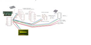 Here I’m going to use 1 dataline and 1 clockline for all components. This saves on the digital out pins from the Arduino. There’s going to be a lot of data shifting through the 4 74hc595’s and the 3 mcp42100’s… A challenge ;)
Sinneb Aurora :: proto 5, one voice with ASR
Where’s the quantize when you need it the most? ;)
Proto 5 has a first ASR (attack sustain release). The MCP42100 (the programmable potentiometer from a previous prototype) generates the enveloppe. Sounds pretty ok, though the attack is a little off which made the playing difficult ;). I will start working on a logarithmic scale instead of a linear scale.
Checkin’ “legato” also.
The schematic:
Third prototype: one voice!
Check this video on vimeo: http://vimeo.com/12988327 :)
This is the third prototype of my DIY synthesizer. I’m using a 82c54 16-bit timer chip for the voice (one chip has three timers, so three voices should be possible). This chip divides a master clock signal (usually in the Mhz range) through a programmable 16-bit value to create a audible frequency.
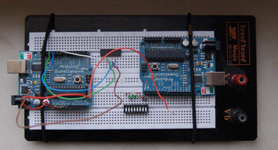
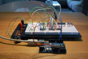
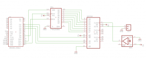
An Arduino Duemilanove interprets the midi (CNY17) and feeds a divider value via a shift register (74hc595) to the 82c54 voice. The crystal oscillator clock ticks at 8Mhz so for a 440Hz pulse waveform (central A) the division value is 18182. This prototype cannot produce notes below midinote 47 (B) because of it’s maximum divider value (16-bit = 65.536). Future prototypes will use a clock divider (arduino itself?)
Oh, my synth-playing-skills are well below par ;)
Very much inspired by the Roland Jupiter / Juno series.
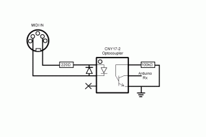
This is the prototype from the previous post, with the midi in hardware solution from tetracon (arduino forum).
Timothy Twillman has developed a great Arduino midi library. Very easy to implement, exactly what I needed. Check it out.
Second prototype using the 82C54
The second prototype uses a 74HC595 shift register to adress the datalines of the 82C54. It is now possible to send different divider values to the 82C54 and thus creating different pulse waveform frequencies.
First proto using the 82C54 CMOS Programmable Interval Timer
Just now I finished the first prototype using one counter on the 82C54 programmable 16-bit interval timer. This timer divides the masterclock by a programmable 16-bit integer (0-65535). When dividing a crystal masterclock, a very stable and precise pulse waveform can be achieved.
First DCO prototype
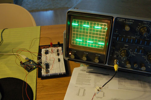
This first DCO prototype uses the Arduino 16 bit timer (timer1) and the midi-in solution from Kuk on the Arduino forum
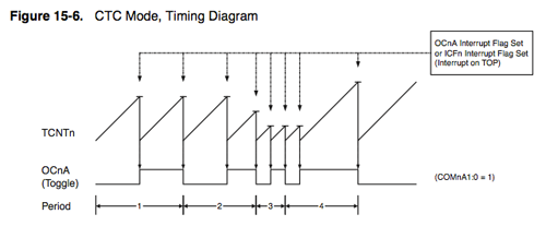
The Arduino has a hardware 16 bit timer (timer1). This timer offers 15 different counting modes. One of these modes is the so called “Clear Timer on Compare Match (CTC) Mode” (Mode 4):
will have to go DCO
It is going to be very difficult to get a decent and stable frequency out of the prototype. I even tried removing the MCP42100 (which is obviously not created for this purpose, will use it later again in the filter), which only resulted in a little more stability. Still drifting around 3 hz when tuning at 440hz. Not acceptable for me, so I’ll go the DCO road. Inspired by the Roland Juno 106:drifting…
The prototype is making noise and I’m tuning it to musical notes. Unfortunately the drift of various components is to high to maintain a stable tuning :( For example my 440hz A tuning: The ppm (temperature stability) of the XR2206 is 20ppm/C, fine. The ppm of the DAC is 0.16ppm/C, even better. The ppm of the digital potentiometer (mcp42100) is 800ppm/C! That number explanes the variation in tuning. Off to find a solution!Arduino midi monitor
When using the Arduino board with midi in, it’s necessary to set the baudrate to the midi standard of 31250. Unfortunately, this is a non-default baudrate so the Arduino Serial Monitor cannot display this serial data. Other solution are also dependent on standard baudrates (here) so these won’t work either. One way of working with this limitation is to switch baudrates during development, not very friendly.
XR2206 making noise!
The XR2206 sinneb 6v is making semi-controlled noise! Check these design schematics and the sounds. Very nice I think ;) The current prototype is a combination of the XR2206 prototype, microprocessor (Arduino) controlled by the MCP42100 and MCP4912. Right now I’m working on a prototype PCB to explore the musical capabilities of the 6v… Keep you posted.
Updated: Eagle schematic & PCB now available
XR2206 function generator
The heart of the sinneb 6v (really, really have to come up with another prototype name). For now one xr2206 function generator produces the base waveshapes for the 6v. The xr2206 is, according to the datasheet, capable of producing high quality sine, square, triangle, ramp, and pulse waveforms of high-stability and accuracy. For now I’m only using the sine out, but switching waveforms is definitely something I’m gonna include!
MCP42100 Potmeter with SPI
The MCP42100 controls the resistance for the XR2206 function generator. Together with the MCP4921 the MCP42100 determines the output frequency. In such a configuration, it should be possible the generate exact musical frequencies. Testing will begin soon!
MCP4921 12bit DAC voltage controller
The MCP4921 controls the sweep voltage for the XR2206. The sweep voltage and the variable resistor together are controlling the output frequency. Precise musical output frequency should be feasible this way. I will be using this table to check if the frequencies are correct.
LCD prototype
For the LCD I build a prototype following this article on the arduino playground.
Parts:
- MC16021E LCD module (farnell 1220425) (different pinout than the LCD on the arduino playground)
- HEF/CD4094
- 2k2 trimpot
- male header pins
My schematic & PCB layout (eagle):
