Sawtooth VCO design
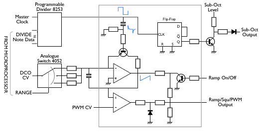
Time for a new post and I have an interesting prototype to share with you. Tom Wiltshire over at electric druid (http://www.electricdruid.net/) made a great writeup about the Roland Juno DCO workings (a true must read). Based upon the diagram I decided to give it a go.
_from http://www.electricdruid.net/, used with permission._
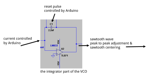
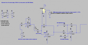
I did some redesign work, since an Arduino is a very handy a capable device for such applications. So, in general the circuit looks and works like this:
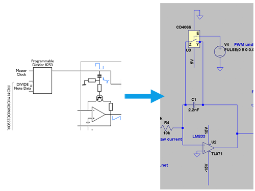
The opamp integrator “fills” the capacitor to generate the upwards ramp. Reset pulses aren’t coming from a 8253 (although I have used those in the past) but from an Arduino generating a PWM wave with a very short “on” time, an almost 0% duty cycle. This results in a direct usable reset pulse for the integrator. This reset pulse is executed by the 4066 switch. When the switch is on, the integrator is set to ground and resets to 0V. The switch is turned off again and the integrating starts again.
Compare both solutions. The Roland DCO uses a programmable divider and a capacitor / resistor / transistor network for the reset pulses (left). My solution uses a PWM signals generated by an Arduino to trigger a 4066 switch ic to reset the integrator (right)
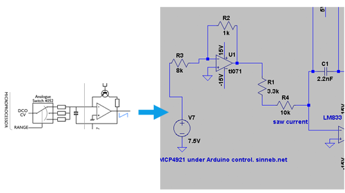
Because the speed of integration varies, the current supplied to the integrator has to vary with that speed. A higher speed (a higher frequency sawtooth wave eg more sawtooths per second) requires more current to nicely reach the upper limit. A lower frequency has to rise slowly towards the upper limit. I solved this with a DAC also controlled by the Arduino. This corresponds to the Roland solution, although the “range switch” is not needed anymore because of the range of the DAC.
The Roland solution had a certain DCO CV which is fed into the integrator via a 4052 switch and a capacitor. My solution uses an Arduino driven DAC (MCP4921) and a opamp buffer to add the required current to the integrator.
In LTSpice, the following circuit was developed and simulated:
click to enlarge. Grab pdf
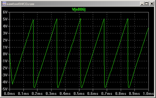
Simulation results in a nice looking, and more important very raw sounding sawtooth waveform.
Look at it
Listen to it (same example as in a previous post)
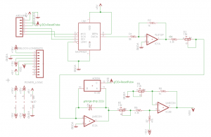
I even build a prototype of this design. The PCB design was made in Eagle.
click to enlarge
Unfortunately I cannot find the Arduino code. The idea is that upon a note change (through midi) the new note frequency gets translated to a PWM frequency with duty cycle as close to 0% as possible. This PWM wave is used to trigger the 4066 switch. Furthermore, the DAC needs to be supplied with a value also depended on the requested frequency. This last ratio was experimentally found by me and put in a reference array.
Work is also needed at the “fix” stage: the level shifters (sawtooth should nicely fold around 0V) and the peak to peak voltage. Upon finding the best values for a certain frequency range, the fix stage can be build around that.
Thanks to everybody on the internet for inspiration for this design. Probably used a lot more sources then the ones mentioned in this article!
