LittleBits synced to Volca Beats’ pulse clock
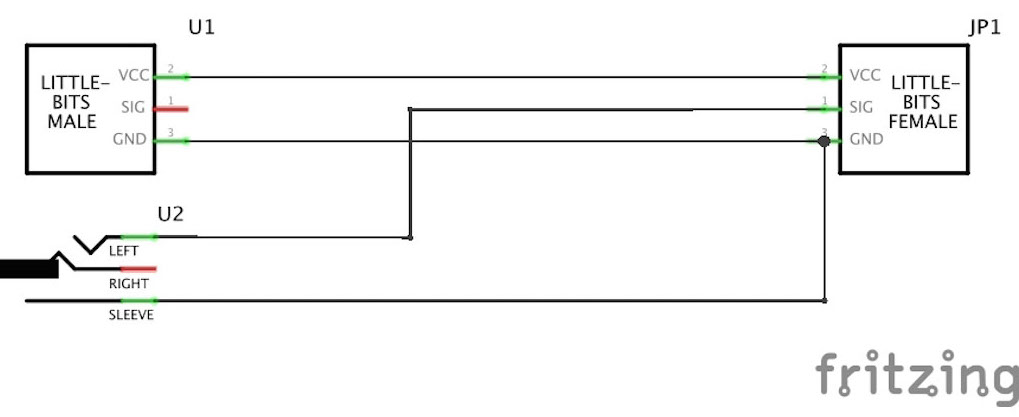
Recently I was fiddling with a set of LittleBits and I was trying to sync these (the LitteBits micro sequencer that is), to my Volca Beats. With the current lineup of LittleBits, this was impossible. Since the Volca Beats has a sync out (0V, 5V pulses with 15ms duration), the solution was not all too difficult. I just took a LittleBits wire, cut it in two, reconnected the VCC and the GND but connected the SIG to the signal connector of an 3.5mm jack plug; this is shown in the schematic below.
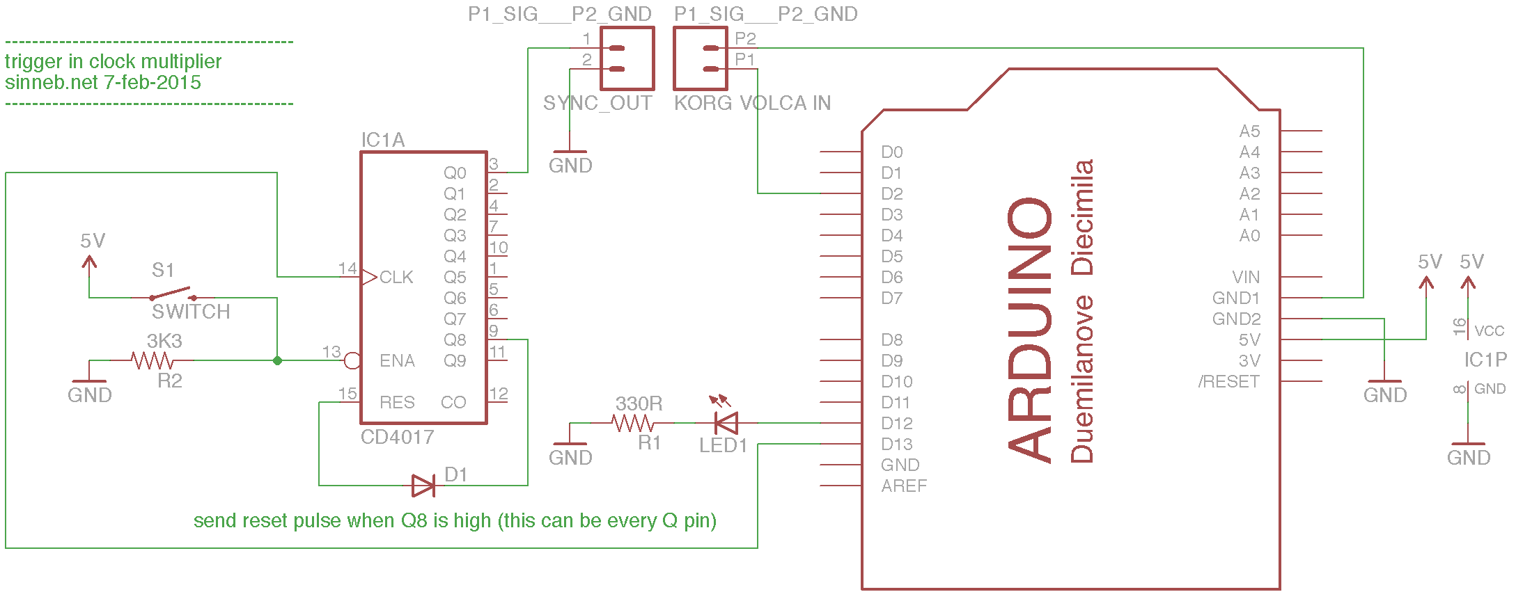
While this was working, I really wanted to have more control over the sync rate, e.g. double, quadruple, or half the BPM from the Volca Beats (or any other clocksource). Solutions using only IC’s or other non-microcontroller components seemed to difficult or complex (if any were found at all, can’t exactly remember). Time to develop some Arduino code than! Using pin 2 as the “sense” pin to detect the incoming pulses, the following code will lock on to that clockpulses, multiply the pulses by 4 or 8 and output the resulting multiplied pulses on pin 13 (easy to debug since the onboard LED will flash in sync with the outputted pulses).
// SINNEB.NET
// trigger in clock multiplier
// Arduino software to read a clock on pin 2 and multiply this clock times 4 or times 8
// output on pin 13

unsigned long delta_trigger_micros;
unsigned long prev_trigger_micros;
unsigned long triggers[7] = {0,0,0,0,0,0,0};

void setup() {
  pinMode(13, OUTPUT);
  pinMode(12, OUTPUT);

  // execute "rising" on RISING interrupt on pin 2
  // pin 2 is connected to the KORG VOLCA BEATS
  // which sends a 15ms, 5V pulse every half beat
  attachInterrupt(0, rising, RISING);
}

void loop() {
  // continuesly scan the trigger array, which is setup by the "rising()" function
  // all 4 of 8 triggers lie in the future
  // when the micros() clock passes a trigger, that trigger is fired (flipPin13)
  // and the trigger is set to 10seconds in the future, waiting to be updated by the "rising()" function
  for(int x = 0; x < 7; x++){
    if(triggers[x] < micros()) {
      flipPin13();
      triggers[x] = micros() + 10000000;
    }
  }
}

void flipPin13() {
  digitalWrite(13, digitalRead(13) ^ 1);
}

void rising() {
  digitalWrite(12, digitalRead(12) ^ 1);
  flipPin13();

  // sync the multiplied clock with the slow clock after a rapid tempo change
  if (digitalRead(12) == HIGH) {
    if (digitalRead(13) == LOW) {
      digitalWrite(13,HIGH);
    }
  }

  // calculate delta between consecutive triggers
  // this "delta_trigger_micros" is used to calculate and activate "in-between" triggers
  delta_trigger_micros = micros()-prev_trigger_micros;
  prev_trigger_micros = micros();

  // split the delta_trigger_micros in a number of subtriggers to
  // multiply the interrupt clock signal
  // every division, a trigger is placed in the trigger array
  for(int x = 0; x < 7; x++){
    triggers[x] = micros() + (((x+1.0)/8.0) * delta_trigger_micros);
  }

}
To divide the Arduino output into different clockspeeds, a CD4017 decade counter is deployed. The Arduino drives the clockpin, a button is connected to the clock enabled pin to “pause” the clock to influence the sync and the reset pin is connected to one of the divider outputs. Depending on the selection of the multiplication by the Arduino (4x or 8x) and the selected divider output, pin 3 of the CD4017 sends out the new clock.
I uploaded 2 Youtube videos to demonstrate this!