Replacing the CA3046 & understanding and replacing the tempco
Let’s get rid of the CA3046, because it’s large and almost obsolete, even the one in a SOIC package (LM3046). The temperature dependant resistor (tempco, 1k, 3300ppm) is also obsolute and very hard to source – so let’s also get rid of that. On this blog, the CA3046 part has been examined in depth, but the tempco part can use some investigation.
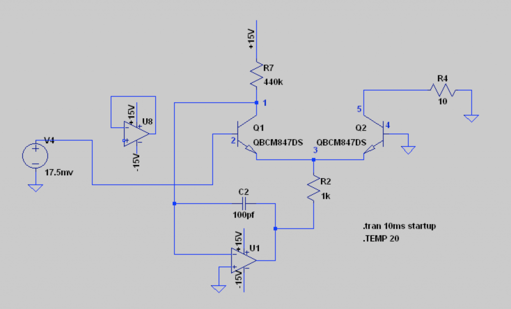
First the CA3046, a General Purpose NPN Transistor Array. The exponential converter only uses the matched pair transistors in this five transistor package. A suitable replacement is the BCM847 matched pair from Nexperia. I’ve read good stories about this transistor pair in exponential converters. So I’ve downloaded the LTSPICE model for the BCM847DS (BCM847 with acceptable reflow soldering package: SOT467) and did some experimentation, very much inspired by Rene Schmitz’s tutorial on exponential converters. Setup:
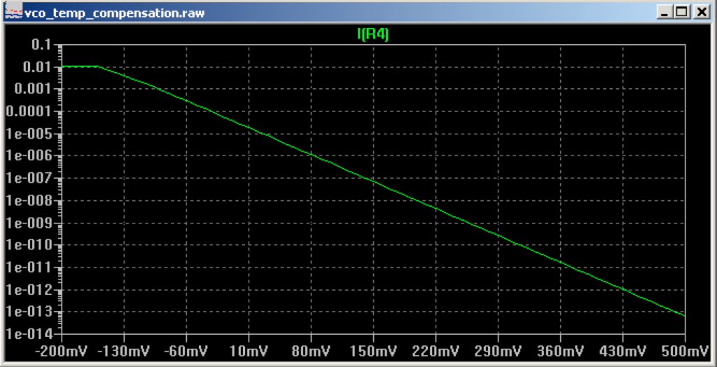
BCM847 matched pair is behaving correctly and shows a decent logarithmic response. DC sweep for V4 from -200mV to 500mV, measured current over R4. Vertical scale is logarithmic:
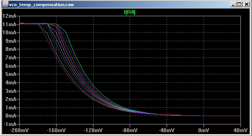
The control voltage for the exponential converter is thus set by voltage source V4. Mmm opamp U8 is not connected at all ;). Through the exponential converter, a voltage V4 related current is put out over R4. This outgoing current is influenced by temperature in a number of ways, but the one under investigation today is the room temperature effect on the thermal voltage. In spice with simulated temperature from 5C till 50C in steps of 5 the current over R4 this looks like this:
The thermal voltage determines the adjustment needed to the voltage from V4 to accurately double the outgoing current over R4. In calculations for a (nice, warm, cosy – but obviously standard?) room temperature of 300K (26.85C):
vt=kT/q -> 1.38064852*10-23 * 300 / 1.60217662 * 10-19 = 25.85mV
vt = Thermal Voltage, k = Boltzmann’s constant, T = temp in Kelvin, q = electronic charge.
Required for an octave: ln(2) * 25.85mV = 17.92mV. So if we increase V4 with 17.92mV, the current over R4 should double. But only if the room temperature, or better said the component package temperature, is 26,85C.
To better understand this relation between temp, thermal voltage, control voltage and current out, I created the following table:
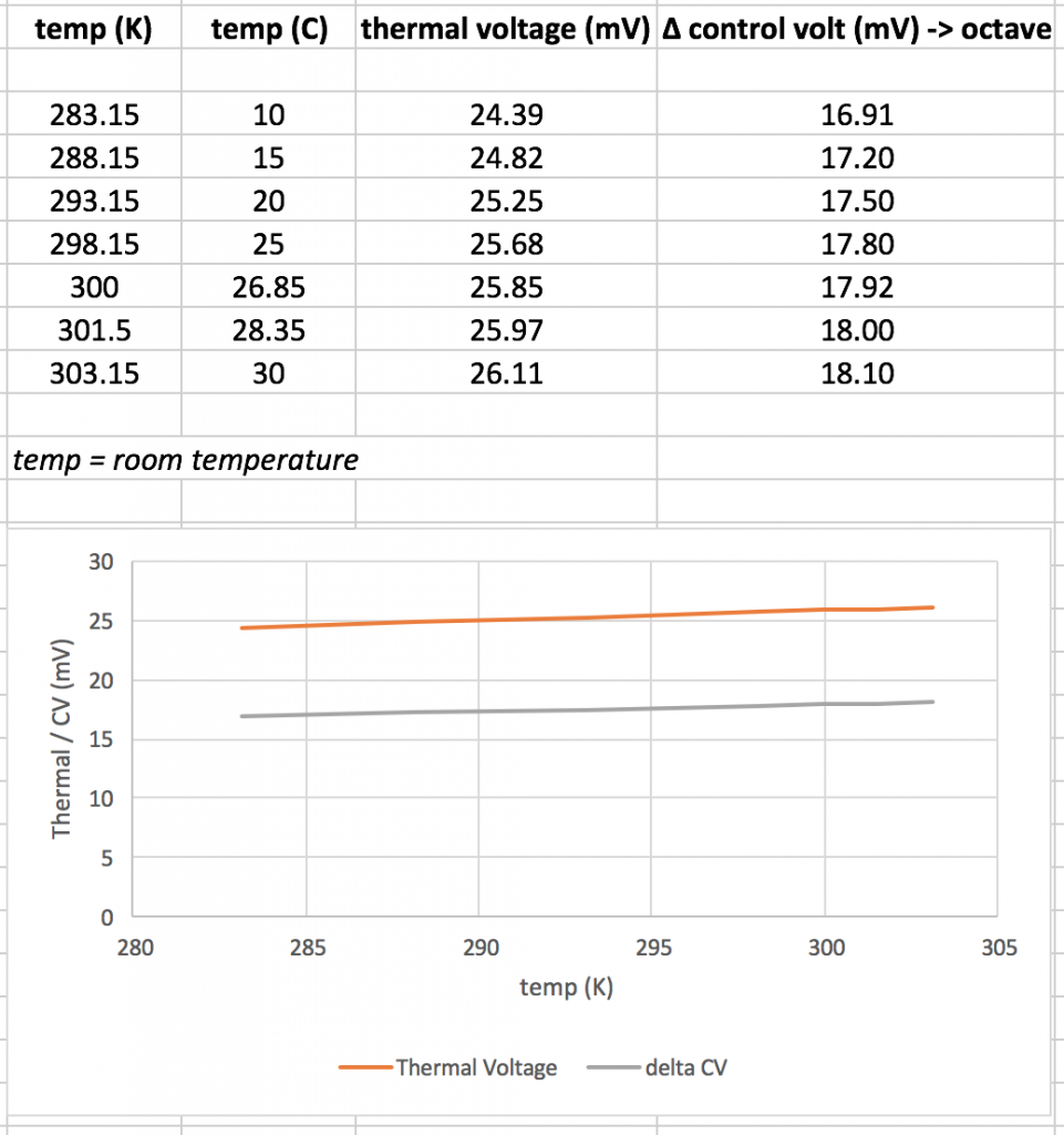
The relation between temperature and thermal voltage and control voltage is linear. Further, per centigrade difference, there is a 0.06mV difference in mV. Instead of just feeding the 1V/oct control voltage from the panel / CV inputs / other inputs to the exponential converter, a temperature correction needs to be made. The exponential converter’s input cannot just be divided down from 1V/oct to 18mV/oct. Let’s have a look at the concerning schematic:
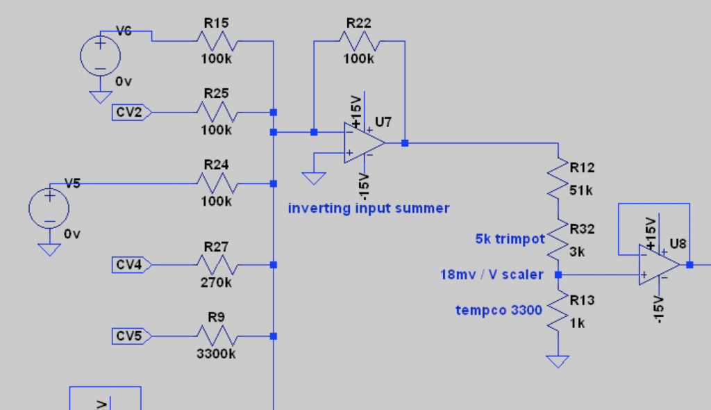
V4 above is in fact this schematic. Multiple CV inputs are summed and inverted. Thereafter, the resulting voltage is divided down to 18mV/oct. The tempco is shown, with a ppm of 3300. This tempco will be replace with a more current device, and based on above insights -> the divider should have a 0.06mV difference per centigrade.
Temperature compensation options: NTC, PTC and Platinum RTD. Platinum RTD is too expensive, PTC has too much tolerance over the resistance and the temperature sensitivity. So, that leaves NTC. I’d like a small NTC SMD component, to mount closely to the BCM847 matched pair and perhaps thermally bond both with resin. A search on Mouser revealed the following part as a good contender: TDK NTCG163JF103F. A narrow tolerance product in 1608 SMD shape, with a B of 3450 with 1% tolerance and a resistance of 10k also with a 1% tolerance. Probably little finetuning is needed with such tolerances.
From the datasheet I plotted the resistance values over temperature for this NTC:
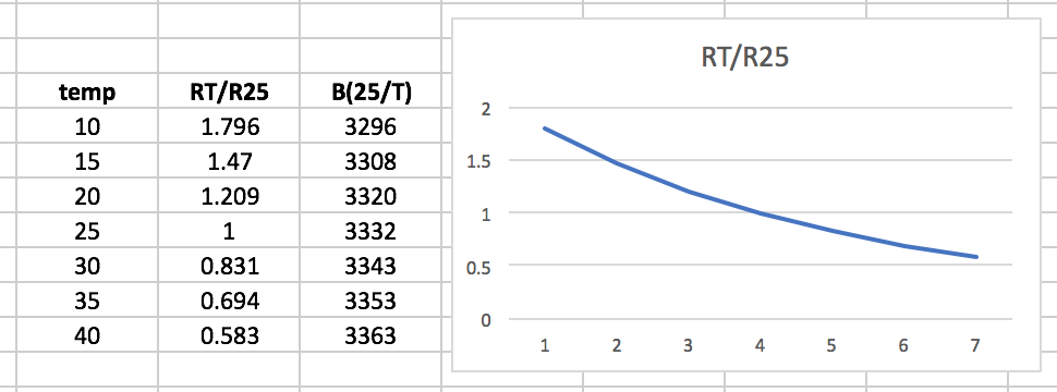
Non linear. Fortunately that will be solvable by adding a fixed value resistor in parallel. Well, that’s up for now!