LCD prototype
For the LCD I build a prototype following this article on the arduino playground.
Parts:
- MC16021E LCD module (farnell 1220425) (different pinout than the LCD on the arduino playground)
- HEF/CD4094
- 2k2 trimpot
- male header pins
My schematic & PCB layout (eagle):
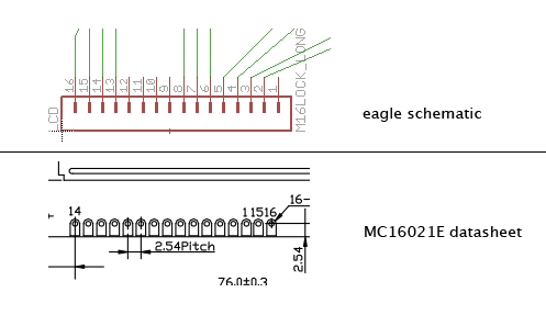
Information regarding the LCD pinout and my eagle layout:
So, LCD pin nr 15 is eagle schematic pin 2, LCD pin nr 1 is eagle schematic pin 3 etc.
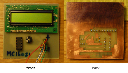
The completed module looks like this:
ok, I should have sanded the PCB a little more, but I was lazy ;) Oh, the trimpot dimensions are off on the PCB so I had to bend the legs (too) much. After a lot of fiddeling I finally managed to fit the trimpot on the PCB.
Arduino code:
// Example use of LCD3Wire library
// Almost a carbon-copy of LCD4BitExample.pde
#include <LCD3Wire.h>
// Arduino pins
#define LCD_LINES 2  // number of lines in your display
#define DOUT_PIN  11  // Dout pin
#define STR_PIN   12  // Strobe pin
#define CLK_PIN   10  // Clock pin

//create object to control an LCD.
LCD3Wire lcd = LCD3Wire(LCD_LINES, DOUT_PIN, STR_PIN, CLK_PIN);

void setup() {
  lcd.init();
  //optionally, now set up our application-specific display settings, overriding whatever the lcd did in lcd.init()
  //lcd.commandWrite(0x0F);//cursor on, display on, blink on.  (nasty!)
  // 0x0C: cursor off, no blink
  lcd.commandWrite(0x0C);
  lcd.clear();
  lcd.cursorTo(1, 0);
  lcd.printIn("freq res lfo var");
  lcd.cursorTo(2, 0);
  lcd.printIn("127  084 127 032");
}

void loop() {
  // empty
}
and the LCD3WireLibrary

