SPI control of AD9833
A few months ago I ordered a MSOP to DIP conversion board including an AD9833 from proto advantage. The AD9833 (LOW POWER, 12.65 MW, 2.3 V TO +5.5 V, PROGRAMMABLE WAVEFORM GENERATOR) looks like an interesting IC, doesn’t cost too much and is perhaps suited for a musical purpose.
Wiring up and controlling the AD9833 took some time and some research but I finally combined the right pieces of the puzzle.

At first I wired up the power section as proposed in the datasheet:

Lots of attention to decoupling and separation of DGND and AGND, which both are a good thing ™ but also clutter my experimental setting on the breadboard. So, time to reduce the number of components with the setup from NXR:
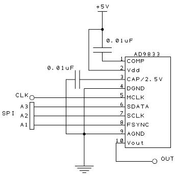
Much better.
Annem did a great job interfacing the AD9837 with the Arduino. Fortunately, the AD9833 has the same interface. I did however make some adjustments. I removed the delay in re-activating the AD9833. I added the Timer1 library to generate the masterclock for the AD9833. This clock runs in the background at ~1Mhz and is made available through pin 9.
/*
AD9837 Pro Generator sample code
This was written in Arduino 1.0.1,
for an Arduino Pro Mini, 5V, 16MHz
Pete Dokter, 9/2/12
Remixed by Anne Mahaffey, 10/8/12
ReRemixed by sinneb, 15th of april 2013

The connections to the AD9837 board are:

FSYNC -> 2
SCLK -> 13 (SCK)
SDATA -> 11 (MOSI)
MCLK -> 9 (Timer1)
+Vin = VCC on Pro Micro
GND -> GND

This code bears the license of the beer. If you make money off of this,
you gotta beer me.
*/

long freq; //32-bit global frequency variable

#include <SPI.h>
#include "TimerOne.h"

// Define the FSYNC (used for SD funtion)
#define FSYNC 2


void setup()
{
 Timer1.initialize(1);
 Timer1.pwm(9, 512);

 pinMode(FSYNC, OUTPUT); //FSYNC

 Serial.begin(9600); // start serial communication at 9600bps

 digitalWrite(FSYNC, HIGH);

 SPI.setDataMode(SPI_MODE2); // requires SPI Mode for AD9837
 SPI.begin();

 delay(100); //A little set up time, just to make sure everything's stable

 //Initial frequency
 freq = 4000;
 WriteFrequencyAD9837(freq);

 Serial.print("Frequency is ");
 Serial.print(freq);
 Serial.println("");

}

void loop()
{

}
void WriteFrequencyAD9837(long frequency)
{
 //
 int MSB;
 int LSB;
 int phase = 0;

 //We can't just send the actual frequency, we have to calculate the "frequency word".
 //This amounts to ((desired frequency)/(reference frequency)) x 0x10000000.
 //calculated_freq_word will hold the calculated result.
 long calculated_freq_word;
 float AD9837Val = 0.00000000;

 AD9837Val = (((float)(frequency))/16000000);
 calculated_freq_word = AD9837Val*0x10000000;

 /*
 Serial.println("");
 Serial.print("Frequency word is ");
 Serial.print(calculated_freq_word);
 Serial.println("");
 */

 //Once we've got that, we split it up into separate bytes.
 MSB = (int)((calculated_freq_word & 0xFFFC000)>>14); //14 bits
 LSB = (int)(calculated_freq_word & 0x3FFF);

 //Set control bits DB15 ande DB14 to 0 and one, respectively, for frequency register 0
 LSB |= 0x4000;
 MSB |= 0x4000;

 phase &= 0xC000;

 WriteRegisterAD9837(0x2100);

 //delay(500);

 //Set the frequency==========================
 WriteRegisterAD9837(LSB); //lower 14 bits

WriteRegisterAD9837(MSB); //upper 14 bits

WriteRegisterAD9837(phase); //mid-low

 //Power it back up
 //AD9837Write(0x2020); //square
 WriteRegisterAD9837(0x2000); //sin
 //AD9837Write(0x2002); //triangle

}

//This is the guy that does the actual talking to the AD9837
void WriteRegisterAD9837(int dat)
{
 digitalWrite(FSYNC, LOW); //Set FSYNC low
 delay(10);

 SPI.transfer(highByte(dat)); Serial.println(highByte(dat));
 SPI.transfer(lowByte(dat)); Serial.println(lowByte(dat));

delay(10);
 digitalWrite(FSYNC, HIGH); //Set FSYNC high
}
I added a buffering opamp to listen to the generated sinewave. Sounds pretty OK to me. Now off to further investigate the audio possibilities of this IC.